In the fast paced world of PCB and electronics manufacturing, picking the right lens can make or break inspection quality. Low distortion lens stand out for keeping images true to life, especially when spotting tiny defects on circuit boards. This guide dives into why they matter and how to choose one that fits your setup.
Why Low Distortion Matters in PCB and Electronics Inspection
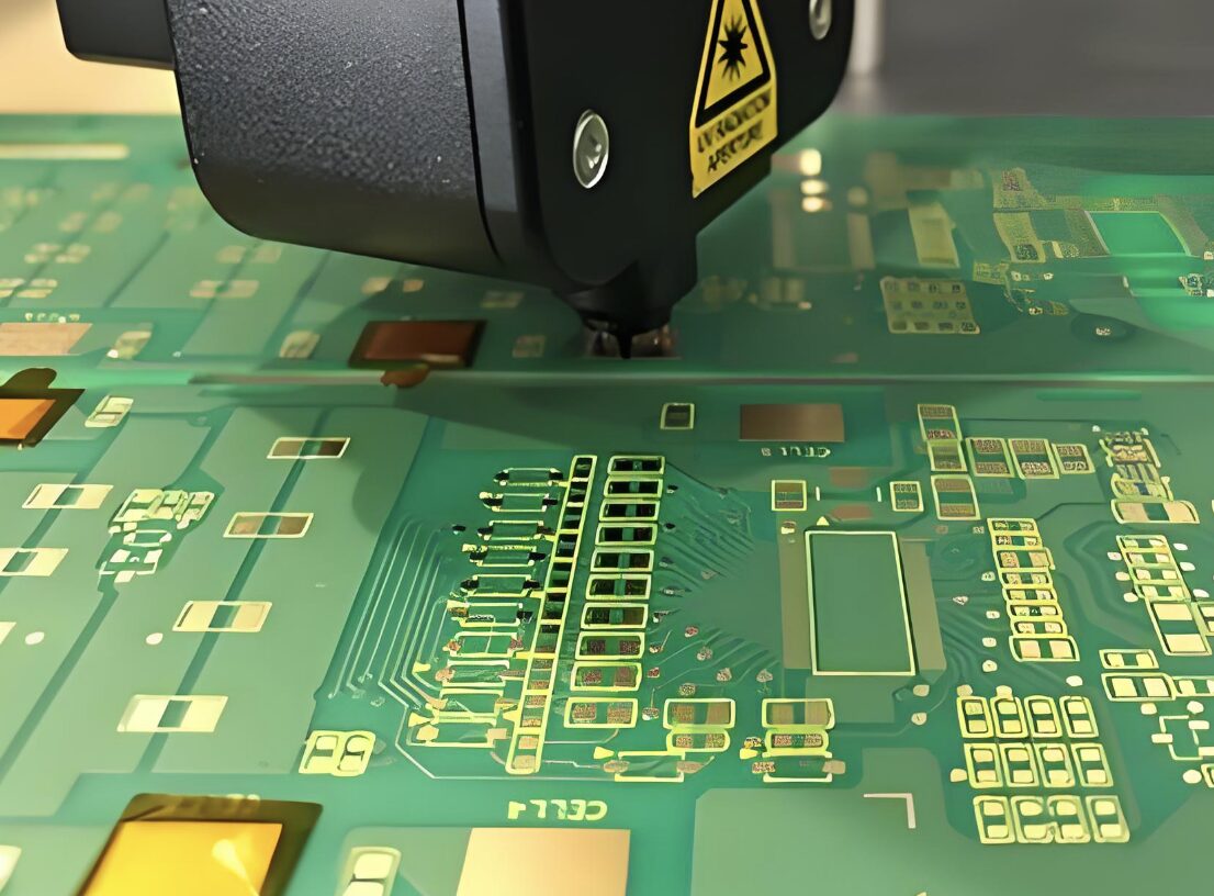
The Role of Machine Vision in Quality Control
Machine vision systems are the backbone of modern production lines. They scan for soldering issues, misalignments, and micro-defects in real time. Without accurate optics, even the best cameras miss flaws that could lead to product failures down the line. A single overlooked crack in a solder joint might cause an entire batch recall.
How Distortion Affects Measurement Accuracy
Distortion warps images, turning straight lines into curves. Barrel distortion makes edges bulge out, while pincushion pulls them in. In PCB inspection, this messes with dimension readings. For instance, a component that measures 2mm might appear as 1.8mm, throwing off automated checks.
Optical distortion
Optical distortion happens when the magnification varies from the center to the edges of the field of view.
As defined in optics, it’s the deformation where actual image height (Y’) differs from the ideal (Y’0 = tanθ), calculated as DIST = [(Y’ – tanθ) / tanθ] × 100%. TV distortion, often used in practice, measures visual effects like RIAA TV Distortion = ΔH/H × 100% for vertical or horizontal shifts.
These can stack up in high volume runs, leading to false positives or negatives.
Benefits of Low Distortion Optics in Precision Electronics Manufacturing
Low distortion lenses deliver consistent geometry across the image. This cuts down on calibration time and speeds up processing in software. In precision manufacturing, they ensure reliable defect detection, boosting yield rates. Plus, they handle complex boards with multi-layers better, reducing rework costs. I’ve seen cases where switching to low distortion optics shaved hours off daily inspections, though that’s not always the norm.
Key Optical Parameters to Consider When Choosing a Lens
Distortion Rate — Keeping Geometry True
Aim for lenses with distortion under 0.5%. This keeps geometry accurate for measurements. In optics, positive distortion below 2% and negative above -3% is tolerable for human eyes, but machines demand tighter specs.
F-theta distortion, common in wide angle lenses, uses [(Y’ – fθ) / fθ] × 100%, where shorter focal lengths amplify distortion.
For PCBs, low rates prevent errors in edge detection.
Resolution and MTF — Seeing Every Solder Line Clearly
Resolution tells how fine details the lens captures, often in line pairs per millimeter. MTF (Modulation Transfer Function) graphs sharpness across frequencies. High MTF means crisp solder lines and traces, even at edges. Pair this with your sensor’s pixel size for best results. Skimp here, and blurry images hide defects.
Focal Length and Field of View — Matching Lens to Sensor and Board Size
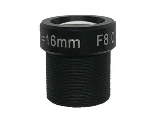
Focal length sets the field of view. Short lengths cover wide areas for full board scans; longer ones zoom in on components. Match it to sensor size to avoid cropping. For example, a 2/3″ image format 6.0mm F4.0 m12 s mount macro board lens might give 67° FOV, perfect for mid-sized PCBs. Get this wrong, and parts fall outside the frame.
Aperture and Depth of Field — Balancing Sharpness and Brightness
The f-number controls light intake and depth of field. Lower f-stops brighten images but narrow focus depth. In industrial setups, f/2.8 often balances sharpness across varying board heights. Too shallow a depth, and uneven surfaces blur out.
Chromatic Aberration — Maintaining Color and Edge Accuracy
This aberration shifts colors, smearing edges in multi-layer PCBs. Achromatic lenses correct for two wavelengths; apochromatic for three. They keep colors true and edges sharp, vital for identifying material differences or defects in color coded components.
Practical Selection Tips for Engineers
Matching Lens to Camera Sensor (C Mount, M12 Mount, etc.)
Compatibility is key. C mounts, with a 17.526mm flange distance and 1-inch thread, suit many industrial cameras. CS mounts are similar but shorter at 12.5mm thread, optimized for smaller sensors in surveillance. M12 mounts (S mounts) fit compact setups with 12mm distance, ideal for lightweight systems. Use adapters for mixes, like C to CS, but avoid direct swaps. Check for vignetting—dark corners ruin inspections.
Evaluating Environmental Durability
Factories aren’t gentle. Look for lenses with metal housings that resist vibrations and temperature swings from -30°C to 85°C. Anti-vibration features prevent focus shifts during operation. Durability extends lens life in 24/7 lines.
Testing and Calibration Practices
Test lenses on your setup before full integration. Shoot grid patterns to measure distortion—SIMA TV Distortion focuses on relative edge-to-center shifts, roughly half of RIAA values. Calibrate with known targets for accuracy. Skip this, and small errors compound over time.
Comparing Lens Types for Industrial Inspection
Varifocal vs. Standard Low Distortion Lenses
Varifocal lenses adjust focal length for flexible zooming, great for varying board sizes. But they might introduce slight distortion shifts. Standard low distortion lenses lock in specs for consistent imaging, better for fixed stations. Choose varifocal when setups change often.
Fixed vs. Variable Focus Lenses
Fixed focus lenses offer peak optical precision with no moving parts—reliable but inflexible. Variable focus allows tweaks for different distances, handy in dynamic lines. Trade-off: variables can wear out faster, but they adapt without swapping lenses.
AICO’s Expertise in Precision Optics
AICO’s Commitment to Optical Accuracy
AICO designs lenses with distortion under 0.1% and high uniformity. Their focus on advanced coatings ensures minimal aberrations. This precision helps in demanding inspections.
Custom Solutions for PCB and Semiconductor Applications
AICO tailors optics for various sensors and systems. Whether for full board or chip-level views, their lenses match formats like 1/1.8″ or larger, optimizing for semiconductor workflows.
Quality Testing and Reliability Assurance
AICO runs in-house MTF, distortion, and environmental tests. This guarantees consistency, from prototype to production. Their processes catch issues early, ensuring reliable performance.
Conclusion
Selecting a low distortion lens boosts inspection accuracy, cuts errors, and ramps up efficiency in electronics manufacturing. It all comes down to matching parameters to your needs. AICO provides that balance with high performance, reliable optics tailored for the job.
FAQs
Q1: What is considered a “low distortion” lens in industrial inspection?
A low distortion lens typically has rates below 0.5%, ensuring minimal warping for precise measurements in PCB checks.
Q2: Can software correction replace low distortion lens design?
Software can fix some distortion, but hardware low designs offer better baseline accuracy and reduce processing load. It’s not a full substitute in high precision tasks.
Q3: How do I choose between telecentric and standard low distortion lenses?
Telecentric lenses eliminate perspective distortion for exact sizing, ideal for metrology. Standard ones suffice for general defect spotting but may need calibration for measurements. Pick based on if you need absolute scale or just visual clarity.